Digital clock using 7490
7490 Pinout
Let's look at the 7490 briefly to see how it works. Here is the pinout:
 |
The 7490 is a decade counter, meaning it is able to count from 0 to 9 cyclically, and that is its natural mode. That is, QA, QB, QC and QD are 4 bits in a binary number, and these pins cycle through 0 to 9,
You can also set the chip up to count up to other maximum numbers and then return to zero. You "set it up" by changing the wiring of the R01, R02, R91 and R92 lines. If both R01 and R02 are 1 (5 volts) and either R91 or R92 are 0 (ground), then the chip will reset QA, QB, QC and QD to 0. If both R91 and R92 are 1 (5 volts), then the count on QA, QB, QC and QD goes to 1001 (5). So:
QD QC QB QA
0 0 0 0
0 0 0 1
0 0 1 0
0 0 1 1
0 1 0 0
0 1 0 1
0 1 1 0
0 1 1 1
1 0 0 0
1 0 0 1
- To create a divide-by-10 counter, you first connect pin 5 to +5 volts and pin 10 to ground to power the chip. Then you connect pin 12 to pin 1 and ground pins 2, 3, 6, and 7. You run the input clock signal (from the timebase or a previous counter) in on pin 14. The output appears on QA, QB, QC and QD. Use the output on pin 11 to connect to the next stage.
- To create a divide-by-6 counter, you first connect pin 5 to +5 volts and pin 10 to ground to power the chip. Then you connect pin 12 to pin 1 and ground pins 6 and 7. Connect pin 2 to pin 9 and pin 3 to pin 8. Run the input clock signal (from the timebase or a previous counter) in on pin 14. The output appears on QA, QB and QC. Use pin 8 to connect to the next stage.

Displaying the Time as Numerals
If you want to display the time as numerals, you need to use the 7447s. Here is the pinout of a 7447, as well as the segment labeling for a 7-segment LED:
 |
 |
You connect a 7447 to a 7490 like this:
- Provide +5 volts on pin 16 and ground on pin 8 to power the 7447 chip.
- Connect QA, QB, QC and QD from a 7490 to pins 7, 1, 2 and 6 of the 7447, respectively.
- Connect 330-ohm resistors to pins 13, 12, 11, 10, 9, 15 and 14 of the 7447, and connect those resistors to the a, b, c, d, e, f, and g segments of the 7-segment LED.
- Connect the common anode of the 7-segment LED to +5 volts.
 |
You will need to have the pinout for the specific LED display that you use so that you know how to wire the outputs of the 7447 to the LEDs in the 7-segment device. (Also, note that the 7448 is equivalent to the 7447 except that it drives common-cathode displays. Ground the common cathode of the LED in that case.)
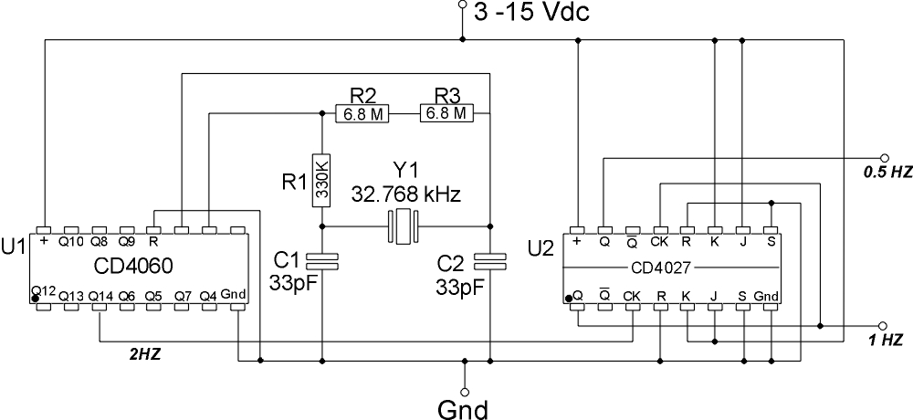
CIRCUIT TO PRODUCE 1HZ CLOCK FREQUENCY
| In principal this circuit is extremely simple. You build a crystal oscillator, and then you divide its output down to 1Hz. The crystal we're going to use here run at 32.768 KHz ( 32768 Hz ). These are commonly called clock, or watch crystals. The significance of the value is that you can successively divide 32768 by 2 and eventually you will get to 1. There are other values that will do this (all multiples of 32768), but this value is very common. That means the crystal is cheap and easy to find. Now we need to divide it down Since divide-by-two is actually a flip-flop, and flip-flops come two to a chip, that means that we'll need 8 flip-flop chips to do all the division (leaving one left over flip-flop). 8 chips means that our circuit will take up a lot of space, and waste a whole lot of power. Luckily there is an easier way. There is a class of CMOS ICs called Frequency Dividers. In essence, they are a long string of flip-flops in a single package. This greatly reduces board space and power consumption. The specific divider chip we're going to use here is the CD4060. This is a 14-stage divider however only 10 of the divider stages are brought out to pin on the chip. One of the benefits of this chip is that it contains the circuitry needed to drive the crystal directly. All we'll need to do is add a couple of capacitors and resistors to make it run. About the only drawback to the CD4060 is that fact that its final output is not the 1Hz that we're looking for, its actually 2Hz. That means that we'll have to add one more stage of division to the chain to get our 1Hz output.
That's actually pretty easy, we'll just add one of the flip-flop chips we were talking about above. Specifically, a CD4027 CMOS Dual J-K Master-Slave Flip-Flop. Since we only need one more stage of division we're left with a spare flip-flop, which is a bonus. A 1Hz clock signal is HIGH for a half of a second, and LOW for a half of a second. For many timing applications, like my frequency counter, you actually need a signal that is HIGH for a whole second (so you can count pulses for exactly one second). So simply take the 1Hz signal and feed it into the spare flip-flop. The output of that flip-flop will be 0.5Hz, or HIGH for one second, and LOW for one second. | |||||||||||||||||||||||||||||||||||||||||||||||||||||||||||||||||||||||||||||||||||||||||||||||||||||||||||||||||||||||||||||||||||||||||||||||||||||||
|
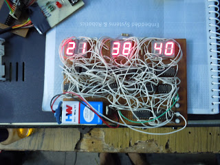
and implementing above my DIGITAL clock is ready


Great job!!!!!!
ReplyDelete